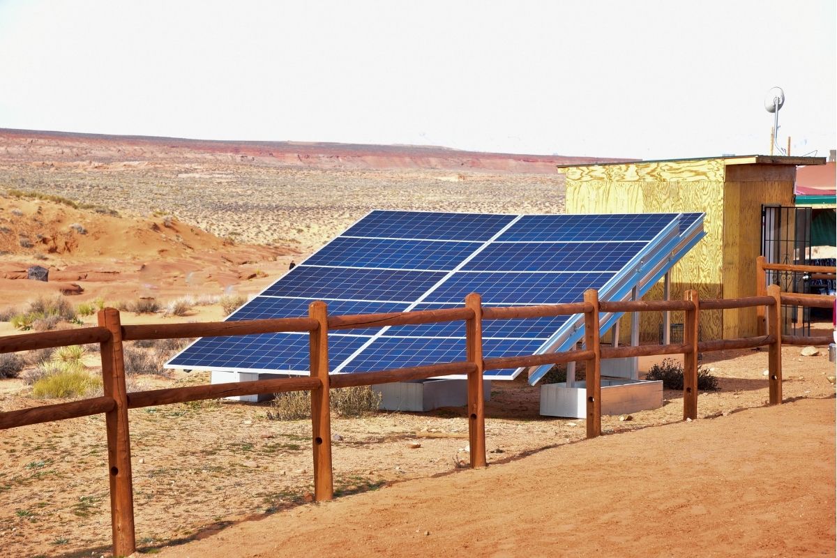
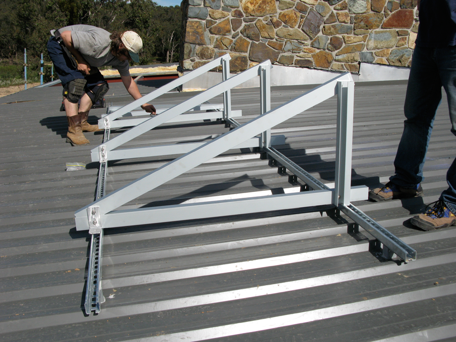
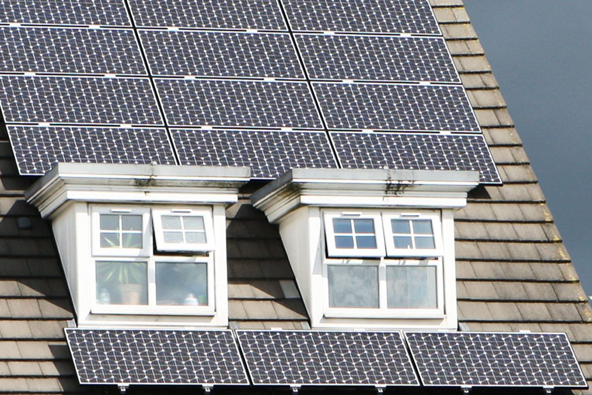
The innovative technique of INOX solar keeps us in sync with every European home and commercial spaces. It contributes to reducing installation costs, simplifying installation methods, and protecting solar installers from the risk of injury and fatigue.
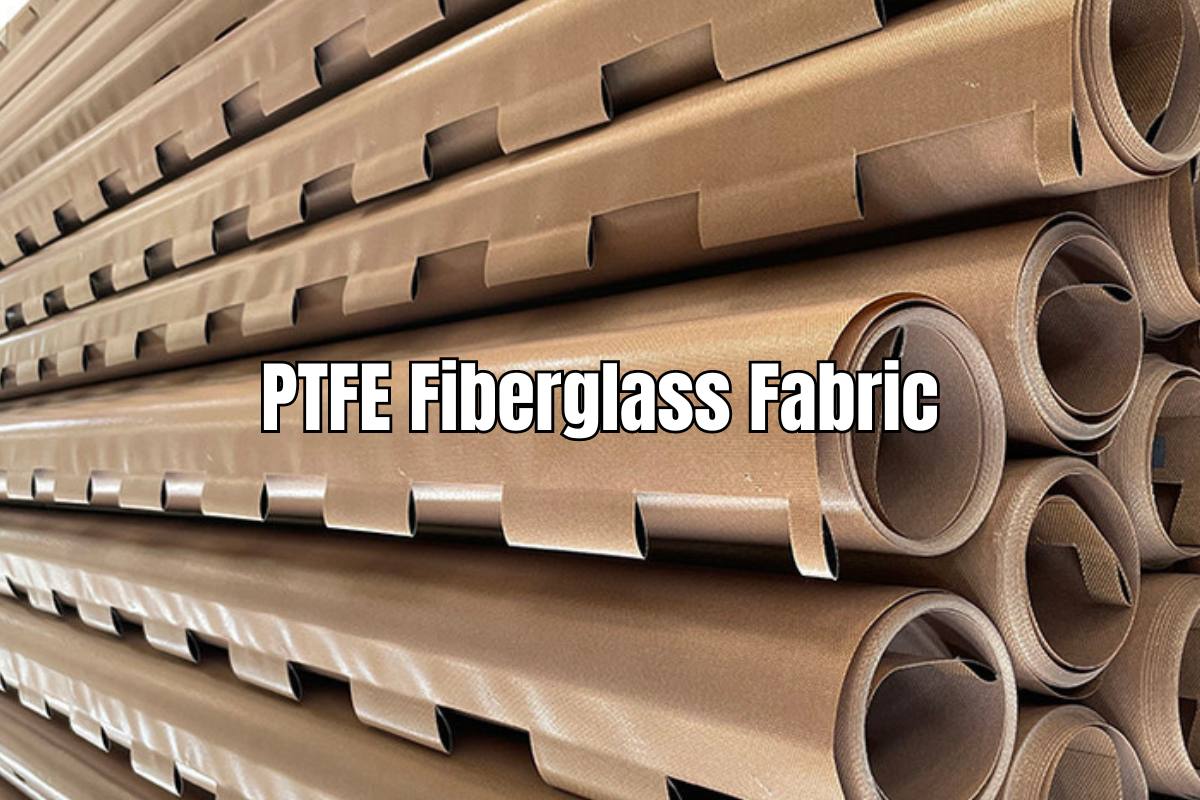
The Role of PTFE Fiberglass Fabric in the Solar Industry
As the solar industry continues to expand, the quest for materials that can enhance efficiency and durability in solar panels becomes increasingly critical. Among these, PTFE (Polytetrafluoroethylene) fiberglass fabric stands out for its unique properties. Let’s talk about how PTFE fiberglass fabric is used in the solar industry, its benefits, the potential it holds for future solar applications, and important safety considerations such as managing the risk of fiberglass fibers staying in the skin for workers handling these …